
Press Photos
WACKER provides you with free photos for editorial purposes. Please send us a screenshot or a copy of the printed publication. Use the selection box to find photos of the Group and its products, as well as their applications. Click the desired category to receive an overview with thumbnails. You can then order the photos you need via e-mail.
Category
Reset perimeterClick the desired category to receive an overview with thumbnails.
You can then order the photos you need via e-mail.
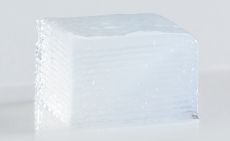
Fig. 04a – d: Picture_Series_3D_Printing
The WACKER 3D process works like an ink-jet printer: the nozzle deposits a drop of silicone precisely at the point determined by the computer program (images 4a and 4b), generating a molded three-dimensional silicone part layer by layer from the virtual drawing (images 4c and 4d).
Order photo
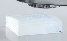
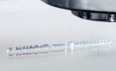
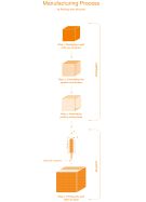
Fig. 03: 3D_Printing_Process
Diagram of the WACKER 3D process. The first step is to design the part with a CAD program. After the spatial coordinates have been calculated (step 2), the printing instructions are generated (step 3). Then, the printer robot follows the instructions exactly and prints the silicone layers dot by dot (step 4). In this way, the virtual CAD model is transformed into a three-dimensional silicone part, layer by layer.
Order photo